
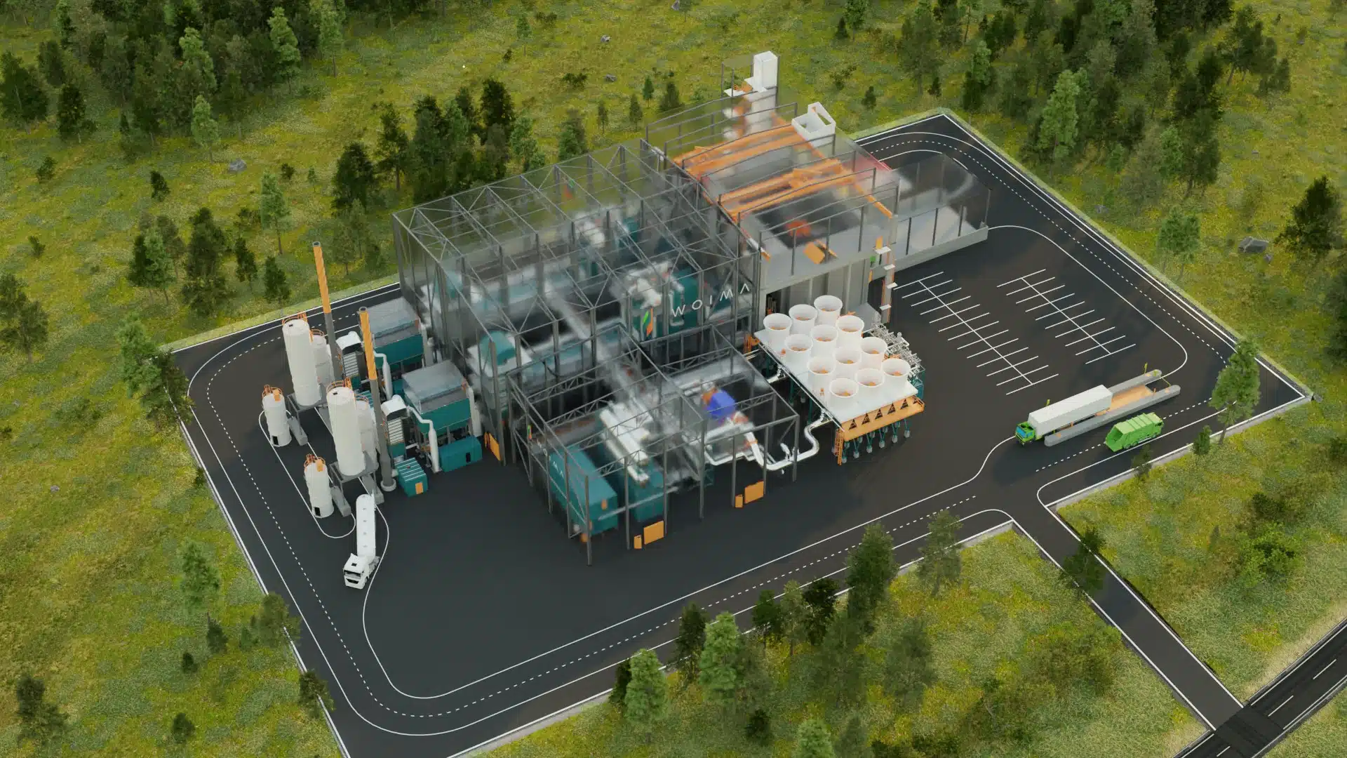
wasteWOIMA® – THE MODULAR WASTE-TO-ENERGY POWER PLANT
The modular waste-to-energy power plant consists of one to two WOIMAlines with the following parameters
• Fuel power 15 or 20 MWfuel
• Thermal efficiency ~88 %
• Electrical efficiency ~25 %
The plant produces (15/20 MWfuel models respectively)
• Steam 18 / 24 tons / h (400°C @ 40 bar(g)) OR
• Electricity 3.7 / 5.0 MWe (gross) / 3.3 / 4.5 MWe (net) OR
• Electricity 1.9 / 2.2 MWe (net) and thermal energy 10.0 / 13.3 MWth
Out of 100 / 130 tons of Refuse Derived Fuel (RDF) or 130 / 170 tons of Municipal Solid Waste (MSW) per day.
Municipal Solid Waste (MSW) is available in abundance everywhere in the world. It offers several business opportunities in reuse, recycling and incineration for energy. Yet, it remains an under-utilized resource, especially in the emerging countries, which would benefit the most of a local energy source. Similarly, the solution reduces the quantity of waste placed in landfills and improves people’s health and general living conditions.
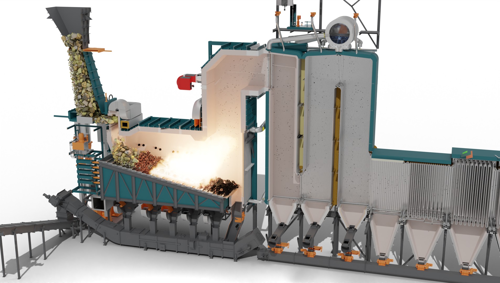
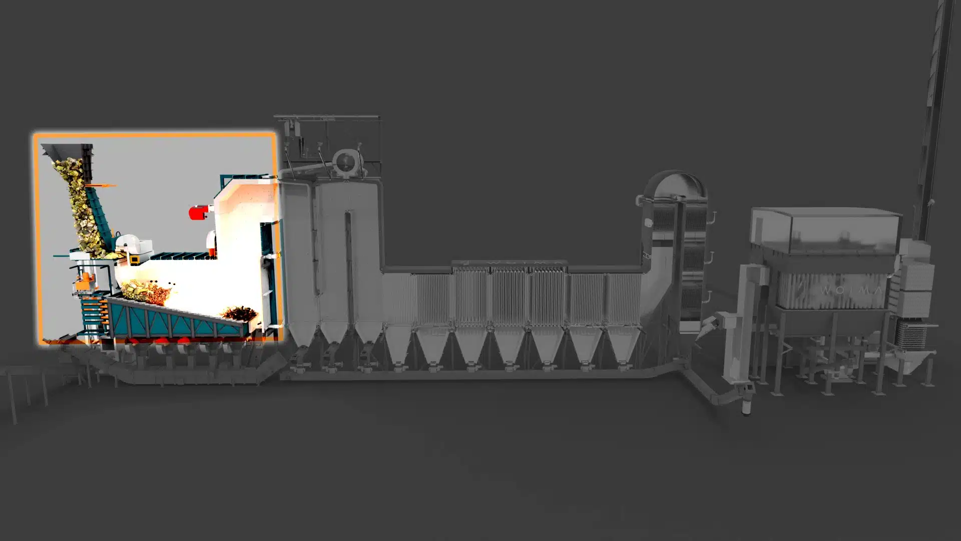
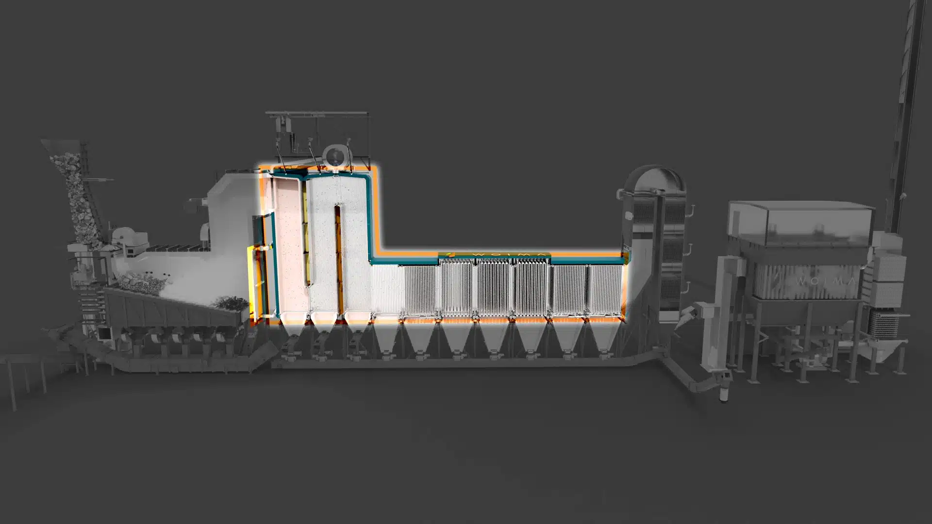
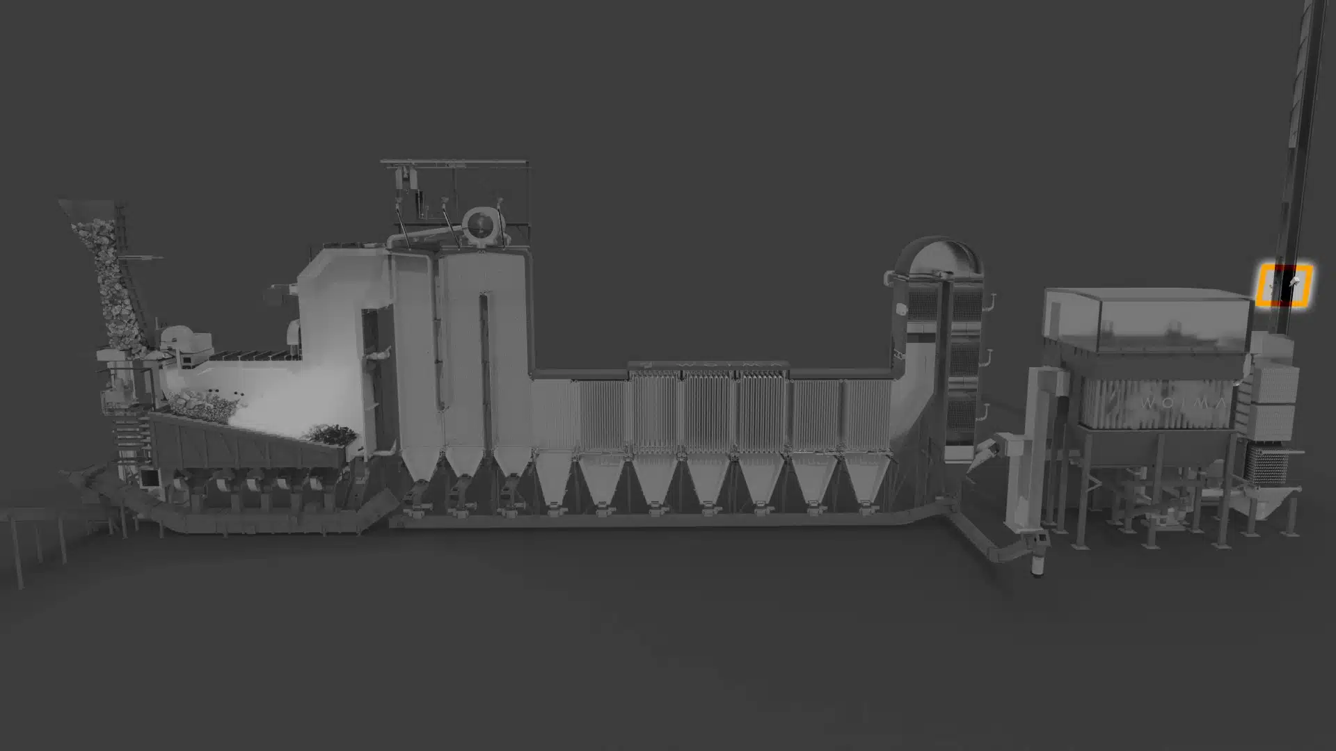
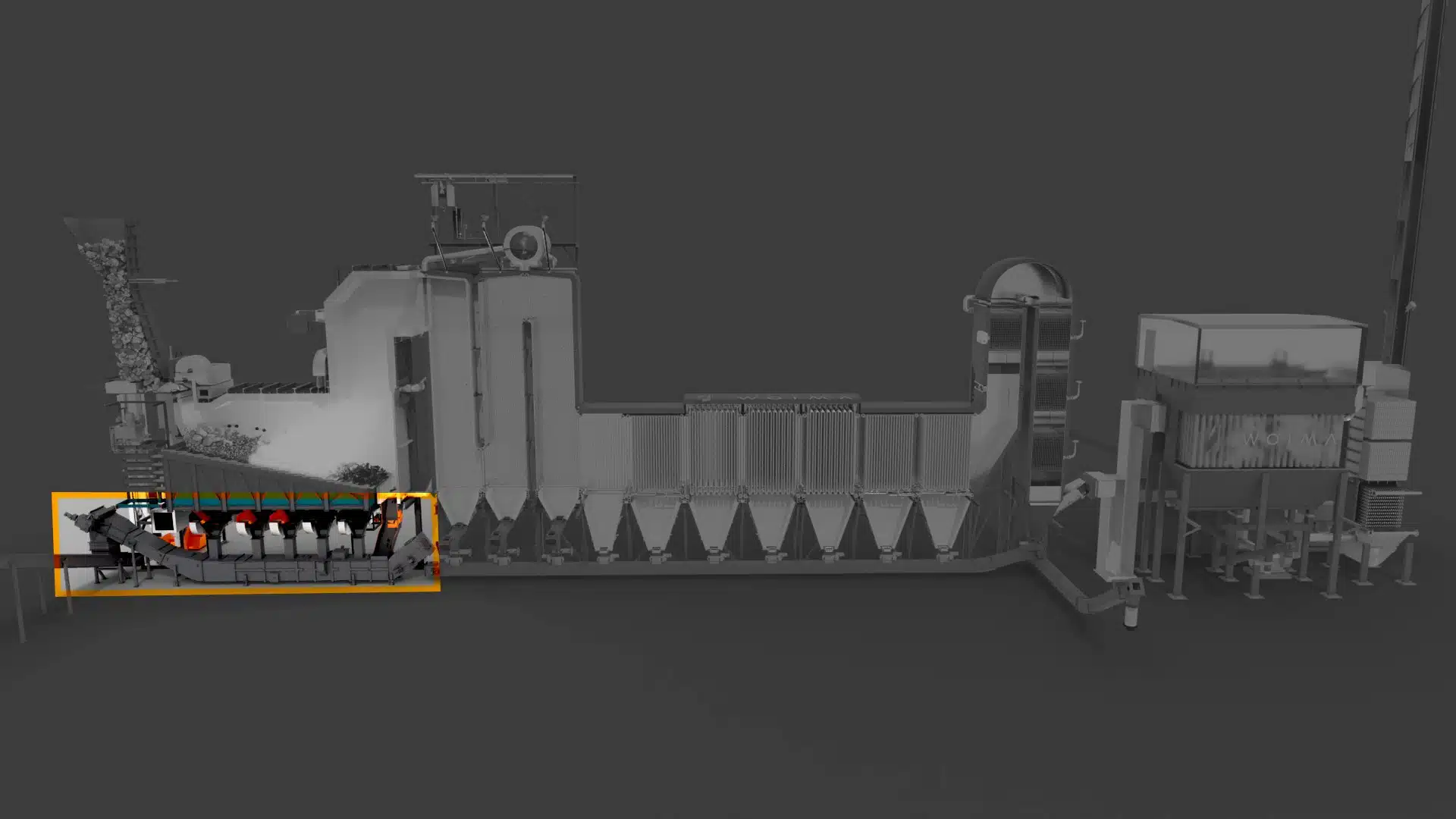
1. Waste Incineration
The wasteWOIMA® W2E power plant technology is based on grate combustion. The purpose of the combustion grate system is to incinerate different kinds of heterogeneous solid waste fuels flexibly to homogenous flue gas efficiently and with high tolerance for inert materials like metals, glass, and sand. At the moving grate, the fuel is dried, ignited, and combusted. The fuel inside the combustion chamber is conveyed and mixed by a reciprocating step grate. The grate is divided into independent hydraulic-cylinder-actuated grate zones with below mounted ash hoppers and primary air feed.
The purpose of the combustion air system is to provide the correct amount of combustion air to the fuel combustion process at the grate and in the combustion chamber optimally phased for combustion control, temperature, and flue gas emission control.
There are two different types of grates available depending on the fuel lower heating value, LHV. The air-cooled grate is designed for fuels with a LHV of 7-17 MJ/kg. The partially water-cooled grate is designed for fuels with a LHV of 14-24 MJ/kg. The right grate type is selected based on fuel LHV design point and range.
2. Evaporator System
The purpose of the evaporator system is to evaporate saturated water taken from the bottom of the steam drum to saturated steam and to separate the steam from the water before directing it to the superheaters.
The boiler is of natural circulation type, which means that the water and steam circulation is achieved by the difference in density when the water in the boiler is heated. The boiler water is led through downcomers and distributors to the lower parts of the evaporative surfaces. The combustion heat of the grate and flue gas is used to heat the circulating water in the gas-tight membrane walls and boiler bank surfaces. When the water starts to evaporate, its density decreases and water-steam mixture flows up through the risers back to the steam drum. Steam drum internal separate the water droplets from the water-steam mixture, resulting in saturated dry steam. Separated water returns back to the circulating system and saturated steam is led to the superheater system.
The sizing of the evaporative vertical flue gas passes of the boiler is determined based on the design flue gas amount, flue gas quality and the required evaporation capacity. The heat released in the passes is transferred through the wall tubes to the water / steam circulation.
Horizontal pass walls and roof are connected to the evaporative circulation. The downcomers distribute boiler water from the steam drum to the inlet headers of the system.
Boiler banks are connected to the evaporative circulation. The downcomers distribute water to all of the boiler banks.
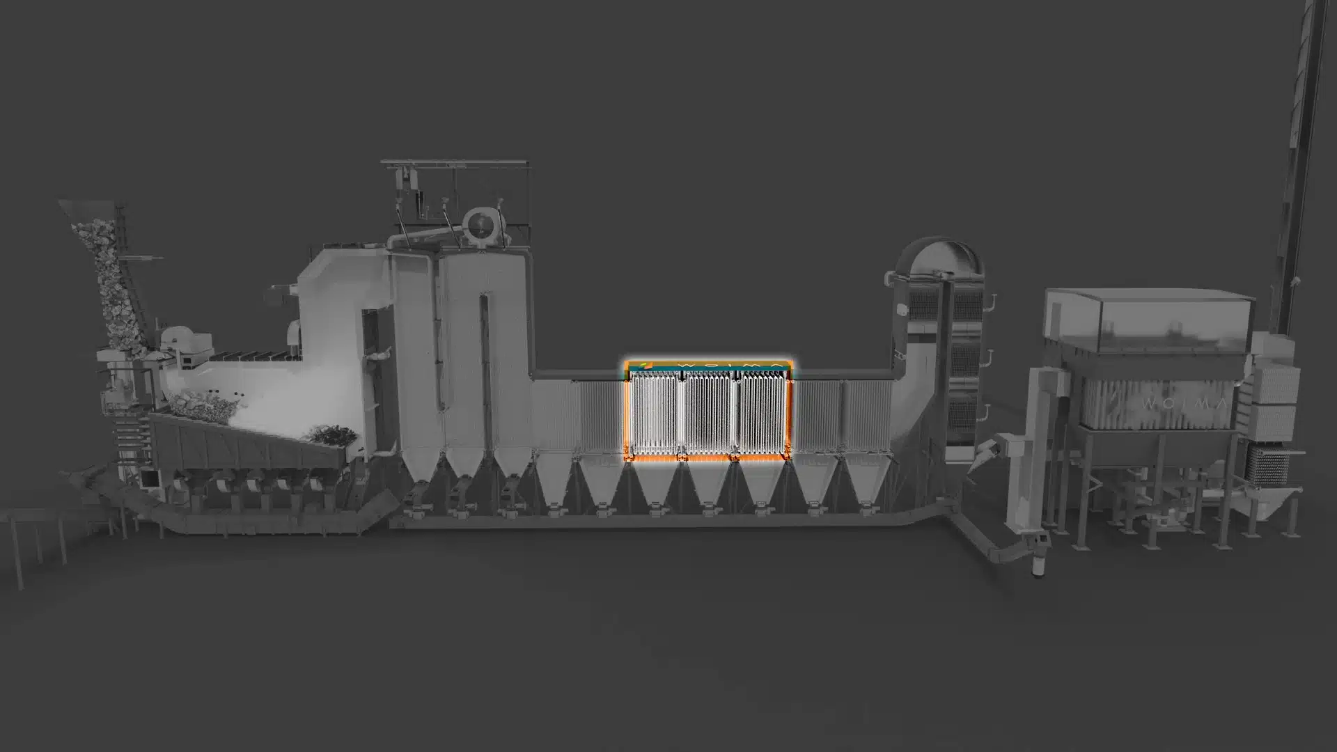
3. Superheaters
The purpose of the superheaters is to heat up the saturated steam formed in the evaporation section of the boiler to the design live steam temperature. The superheaters are divided into sections. There are desuperheaters between the sections to control the steam temperature at different operating conditions.
All superheaters are vertical, convective-type heat exchangers located in the horizontal convection pass of the boiler. The tube pitch of the superheaters is designed and selected to provide a trouble-free performance even with fouling fuels.
The steam temperature in the superheaters and the temperature of the live steam are fine-tuned in the desuperheaters by mixing feed water spray with the steam. The high-pressure spraying water is taken as a branch from the feed water lines.
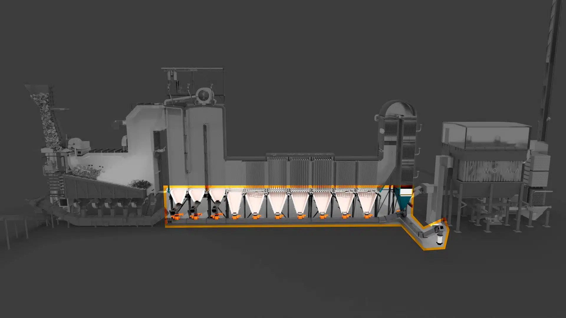
4. Economizers
The purpose of the economizers is to improve the boiler efficiency by utilizing heat from the flue gases to preheat the feed water of the boiler before it is fed to the steam drum. Economizers are located in the flue gas stream in between the evaporative section and the flue gas treatment (FGT) system. There is also a economizer located downstream of the FGT to further improve the boiler thermal efficiency. In the economizers the flue gases are cooled to a temperature required by the FGT system and the feed water is heated close to saturation temperature.
5. Flue Gas Treatment System
The purpose of the flue gas treatment (FGT) system is to reduce the flue gas emissions of the power plant. Flue gas generated from burning waste fuels, contains pollutants such as particulates, dioxins, furans, sulfur dioxide, nitrogen oxides, hydrogen chloride, hydrogen fluoride and heavy metals. Flue gases can substantially affect the local and regional air quality if left untreated.
The FGT system adheres to the EU emission regulation as defined in the Industrial Emissions Directive 2010/75/EU and in the subsequent Best Available Techniques (BAT) Reference Document for Waste Incineration. All waste incineration flue gases that are formed in the incineration process are treated and cleaned to meet the regulation requirements.
Flue gas treatment is a multi-stage process including the following phases:
1. Most toxins (namely dioxins and furans) are burnt out in the boiler by ensuring temperature of over 850°C for a period of two seconds after the last injection of combustion air.
2. Sodium bicarbonate (NaHCO3) or hydrated lime (Ca(OH)2) and activated carbon is mixed with the flue gas in a reactor just prior to the baghouse filters. They neutralize acids and toxins, absorb heavy metals, and coagulate the particle matter that is then collected in the fabric filters.
3. Ammonia water solution or urea is sprayed into the flue gas to reduce nitrogen oxides (NOx) into harmless nitrogen compounds. For low emission limit a Selective Catalytic Reduction (SCR) process and ammonia water is used. Higher limits can typically be achieved with urea spray in the combustion chamber.
The treated flue gas containing mostly carbon dioxide (CO2) and water vapor (H2O) is then directed to the stack, where the continuous emission monitoring system (CEMS) is used for monitoring the emissions in the cleaned flue gas.
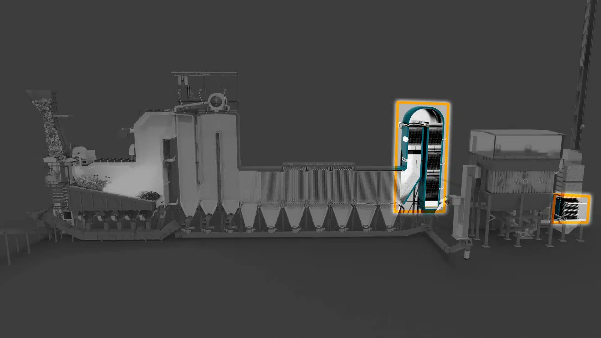
6. Continuous Emission Monitoring System (CEMS)
The purpose of the continuous emission monitoring system (CEMS) is to monitor the flue gas emissions from the power plant to the ambient air through the stack. These continuous measurements are used for emission control of the power plant as well as for controlling the incineration and the flue gas treatment processes. Emission measurements are a prerequisite for the operation of a waste incineration plant.
The flue gas analysers required for continuous emission control of the power plant are located in a CEMS container at the bottom of the stack. The probes for sampling are installed in the flue gas stack. The samples extracted from the flue gas stream with the probes are directed to the analyzers in insulated and heated sample lines.
The CEMS is continuously monitoring pressure, temperature, flow, solids content, total organic carbon (TOC), hydrogen fluoride (HF), oxygen (O2). carbon dioxide (CO2), water vapor (H2O), carbon monoxide (CO), nitrogen oxides (NOx), sulfur dioxide (SO2), hydrogen chloride (HCl) and ammonia slip (NH3). If required, a optional mercury (Hg) measurement device can be installed
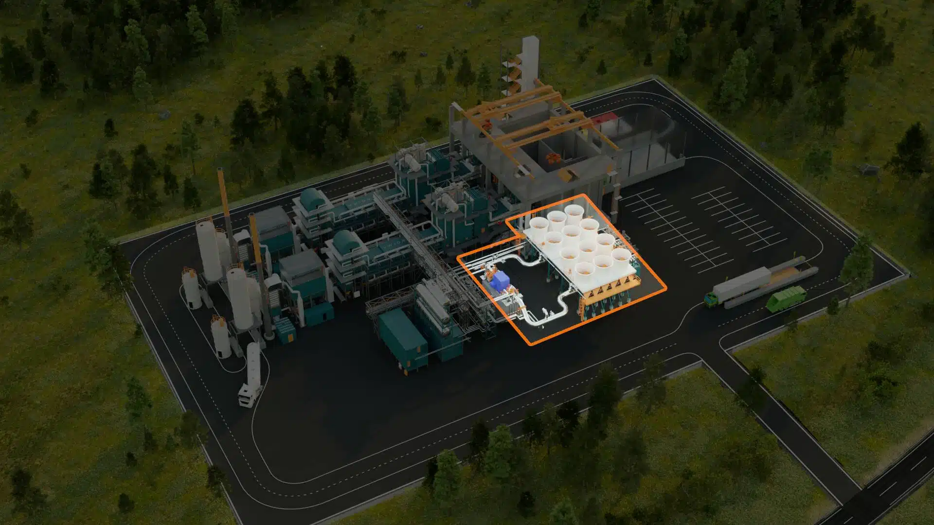
7. Ash Handling
The purpose of the ash and slag removal system is to collect, cool down and remove the slag (bottom ash), boiler ash and fly ash formed in the combustion process. The ashes are separated from the flue gas on the heat surfaces and in the bag house filter and led to extraction points for storage and use.
Bottom ash (slag) is the solid residue remaining after the waste fuel is incinerated on the grate. The bottom ash discharger is used to cool and discharge this solid residue that accumulates at the end of the grate and drops down into the discharge pool. Siftings, particles that fall through the grate during incineration, are also collected into this pool. The cooling water in the pool serves as an air seal for the furnace, preventing flue gas emissions and uncontrolled air leaks. An apron conveyor is used to extract the bottom ash as well as any bulky objects from the pool.
The water used for cooling is separated from the bottom ash by gravity at the conveyor and it drops back into the discharge pool. Top-up water is required to maintain the water level in the discharge pool. The top-up water from blowdown water tank or raw water tank replaces water lost as moisture in the removed slag as well as the evaporation losses.
Fly ash is comprised of the particles formed in the combustion that are transported out of the combustion chamber with the flue gas. Some of the fly ash accumulates on the heat transfer surfaces forming layers that must be removed using a boiler cleaning system. The remaining fly ash is separated from the flue gas in a bag house filter installed in the flue gas treatment (FGT) system after the boiler.
The fly ash removed from the heat transfer surfaces is collected in ash hoppers and discharged into a drag chain conveyor through a rotary valve feeder. The hopper and the valve maintain the gas-tightness of the boiler during ash discharge.
The remaining fly ash and FGT residues separated from the flue gas in the bag house filter are collected from the ash hoppers with a screw conveyor and led to a pneumatic conveyor through a rotary valve feeder. The conveyor transports the solids to the ash handling and storage.
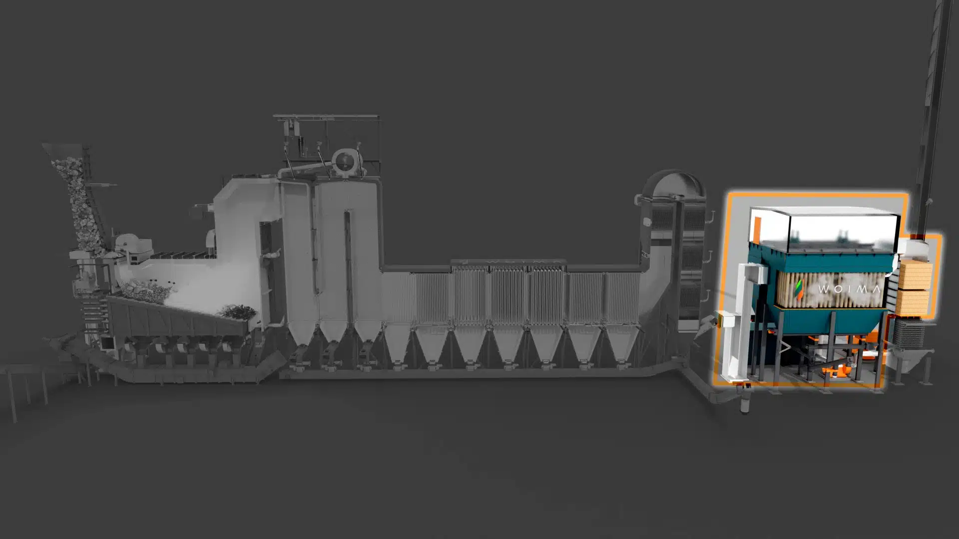
8. Power Generation and Condensing
The purpose of the steam turbine generator set is to generate electricity efficiently from the high-pressure live steam produced in the steam boiler. At the same time, it provides low pressure steam for plant internal use.
In the steam turbine generator, the thermal energy of the pressurized superheated steam produced in the steam boiler is transformed into electricity.
The steam turbine unit can be a condensing turbine used only for electricity generation or a back-pressure turbine in which the steam expands only to a selected pressure level. Required pressure level after turbine unit is selected based on process steam / district heating network requirements. In each case, a condensing system is required.
The purpose of the condensing system is to condense the exhaust steam from the steam turbine or turbine bypass to water and to collect all reusable condensate from the power plant steam and condensate systems and return it in a controlled way to the feedwater tank.
Condensing can be done several methods depending on local conditions, based on available cooling medium and its temperature. In an electricity only plant, air-cooled condensers are used. In a CHP or thermal plant, the steam consumer acts as the condenser.
Benefits
The proven technology and modular structure ensure that the WtE power plant has